
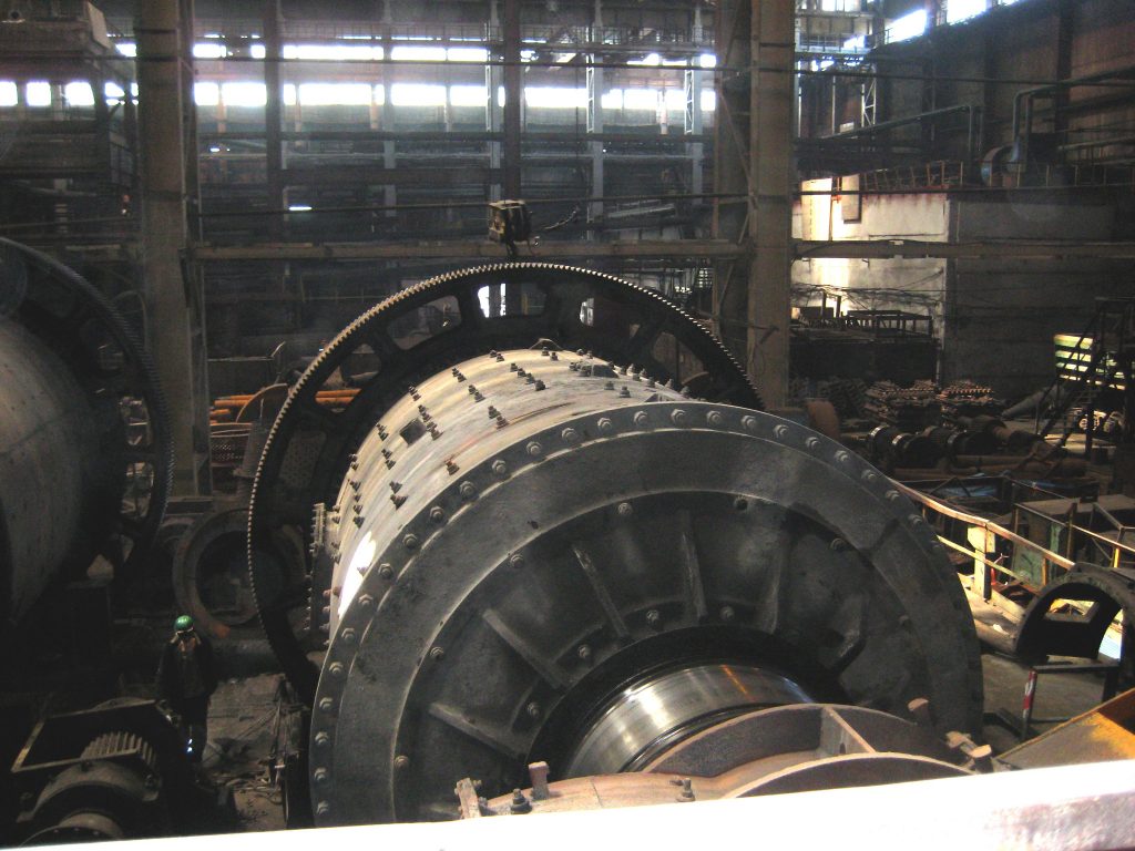
The ball mill is a hollow drum closed with loading and unloading end caps, filled with grinding media and rotated around its axis. The drum of the ball mill (Pic. 1) is a hollow cylinder of steel, lined inside with armor lining plates which protect it from impact and friction effects of the balls and the grinding material. The shape of drum liners has a significant impact on mill’s work. Drum Liners of ball mills operated on a large source material have ribs. For mills operated on the fine materials use lining with small ribs or quite smooth. Height, mutual arrangement and shape of the ribs define force of adhesion the grinding media with the drum and the results of the mill’s work. It is important when the character of the lining surface did not change harshly during its deterioration.
Pic.1. The drum of the ball mill
End caps molded integrally with the hollow pins. On pins planted supporting bandages. The drum is supported by two self-aligning roller through these bandages. Material loaded into the mill through the hopper. The mill is driven by a motor through a clutch, gearbox and flexible coupling. Grinding media followed to the direction of the drum rotation during its rotation, lifted to a certain height and freely fell down or rolled down.
Depending on the method of discharging of the milled product from the mill there are the center unloading mills and unloading through the grille mills.
At mills with center unloading the milled product removed by a free sink through a hollow unloading trunnion. It is necessary for the pulp level in the drum to be above the level of the lower generating unloading trunnion. Therefore mills with center unloading sometimes called drain type mills or mills with high pulp level. The unloading funnel has a slightly larger diameter than the loading funnel to create slope and for maintain a high pulp level in the mill.
Mills with unloading through the grid have a lifting device and it forced to unload the milled product. Therefore, in this type of mills the slurry level may be lower than the unloading trunnion level. Mills with unloading through the grid sometimes called mills with forced unloading or mills with a low level of pulp. This type of ball mill has a grid with openings for unloading crushed material and located in the unloading end of the drum. The grid has radial rib-lifters on side facing to the unloading end cover. Rib-lifters divide the space between the grid and the end cover on a sectorial chambers opened in the trunnion. By rotating the drum ribs act as elevator’s wheel and raise the pulp to the level of unloading trunnion. This device allows to maintain a low pulp level in the mill and reduces the spent time of the material in it due to the decrease of volume of the pulp.
Depending on the shape of the drum there are cylindrical mills and cylinder-conical mills. Cylindrical mills classified into three types: short mills, long mills and pipe mills. Short ball mills have a drum length less than drum diameter or equal to drum diameter. Long ball mills have a drum length more than one drum diameter, but less than three drum diameters. Pipe ball mills have a drum length longer than three drum diameters.

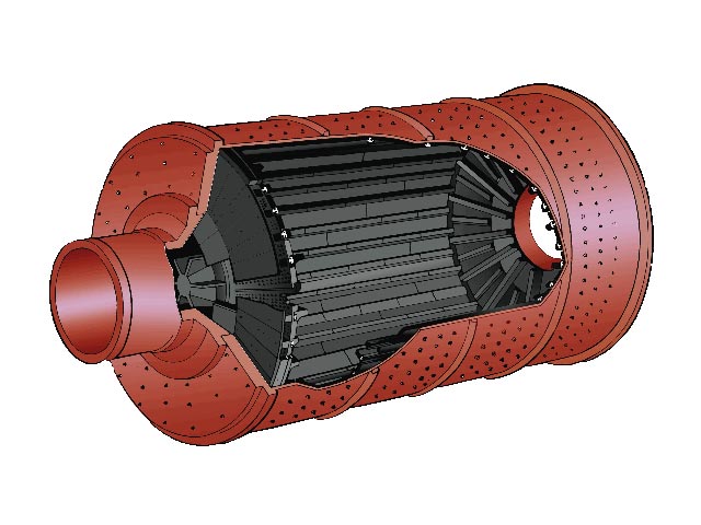
Pic. 2. Cylindrical balls mill
A cylindrical ball mill used for grinding the coarse material. This mill should have a short length because the balls distributed uniformly over the entire length of the mill and during rotation obtained the same pulse. The drum diameter of the cylindrical ball mill should be the greater, the larger the pieces of crushed material.
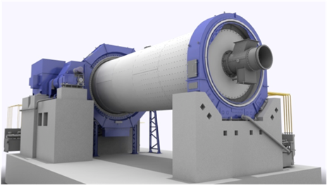
Pic. 3. Pipe ball mill
The balls impact on the milled material longer at the pipe ball mills. The drum of these mills lined with flint blocks inside or flint pebbles on the cement. Material continuously fed by the drum axis through a hopper at one end and leaves at the opposite end of the drum through end wall or holes on drum walls. Pipe ball mill (Pic. 3) provided with a drive with construction similar to the drive of rolling mills. The central drive shaft has milled protrusions and depressions at the ends and enters them into the corresponding coupling. In this arrangement the axial displacement of the mill is not transmitted to the reducer or motor.
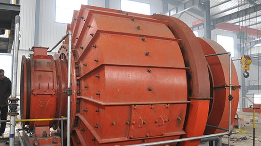
Рiс. 4. The cylinder-conical ball mill
The housing of the cylinder-conical ball mill consist of two cones and a short cylindrical part between them (Pic. 4). This change in the shape of a cylindrical mill is highly advisable, because achieved the proportionality between the force and useful resistance. The peripheral speed of the conical mill drum gradually decreases in the direction from the cylindrical part to the discharge outlet in the same direction reduced lifting angle of balls inside the mill, and consequently decreases their kinetic energy. The amount of milled pieces also gradually decreases as approaching to the place of unloading and this reduces energy consumption for grinding.
Should be noted, the productivity of ball mills depend on the drum diameter and ratio between the diameter and length of the drum. At the short ball mill grinding is a more rough and for grinding fineness a lot of material has to be returned from classifier to the mill, it leads to mill overload. In long ball mills the grinding occurs only at the front and the rest of the balls in the drum only increases power consumption.
Drum mills have one grinding chamber (short and long ball mills) and two or more grinding chambers (long and pipe ball mills). Single-chamber continuous mills are the main equipment at mining and processing plants.